
Technical Drawing Collection
"Exploring the Art of Technical Drawing: A Journey Through Time" Step into the world of technical drawing, where precision and creativity intertwine


All Professionally Made to Order for Quick Shipping
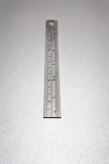
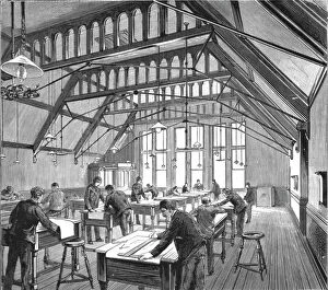
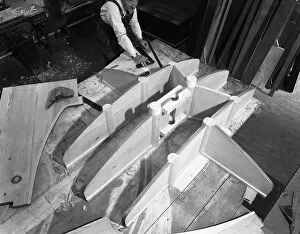
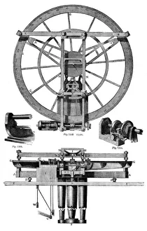
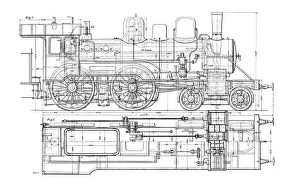
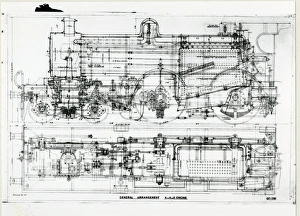
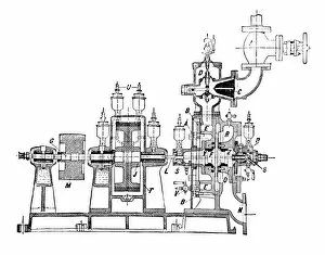
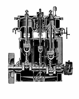
"Exploring the Art of Technical Drawing: A Journey Through Time" Step into the world of technical drawing, where precision and creativity intertwine. With a metal ruler in hand, artists like Michael Walters bring intricate patterns to life at Wombwell Foundry in South Yorkshire, 1963. Travel back even further to witness the birth of innovation with Stephensons' Locomotive in 1887. Although its creator remains unknown, this masterpiece showcases the power and elegance of steam locomotives through wood engravings published in 1877. Delve into history as we encounter Gaspard Monge, a French mathematician whose brilliance is immortalized through chromolitho prints. His contributions to technical drawing revolutionize engineering design. In Germany's drawing office scene from 1936, fresh plans for new works take shape. Witness how meticulous attention to detail ensures flawless execution and groundbreaking developments. Pattern making becomes an art form at Wombwell Foundry in South Yorkshire once again in 1963. Steel molds are meticulously crafted by skilled artists who transform raw materials into functional masterpieces. Edgar Allens steel foundry in Sheffield unveils another glimpse into the drawing office scene of 1964. Here, Michael Walters captures the essence of dedication and craftsmanship that fuels industrial progress. Join a group of foundry staff from Sheffield as they gather around technical drawings - symbols of collaboration and shared expertise - capturing their pride and commitment towards their craft in 1963. Discover Newcomen's steam engine for draining mines from 1956; an invention that forever changed mining operations worldwide. Its elevation showcased through detailed drawings highlights both its functionality and beauty. Finally, marvel at Troughton's dividing engine from the eighteenth century captured elegantly on paper by an unknown artist back in 1886 – a testament to timeless ingenuity that continues to inspire generations today. Technical drawing transcends time.